Scan Multiwell Plates
Imaging Multiwell Plates
Multiwell plates in 6, 12, 24, 48, 96, and 384 well formats can be scanned on the Odyssey M. Be sure to select multiwell plates that fit the Plate Alignment Guide.
Do not attempt to image plates that have a height greater than 23 mm on the Odyssey M.
Proper selection of multiwell plates significantly affects the results of your analysis, because each plate has its own characteristics including well depth, autofluorescence, and well-to-well signal crossover. Some general considerations for multiwell plate selection are provided here.
- Do not use plates with white walls, because the autofluorescence from the white surface will create significant noise.
- For an In‑Cell Western™ Assay, LI‑COR recommends the following plates.
- For adherent cells, LI‑COR recommends a 96-well plate with a clear, flat bottom and black wells, such as the Greiner Bio-One CELLSTAR® Black μClear® Microplate, LI‑COR PN 926-19156 (8 pack) or 926-19157 (32 pack).
- For suspension cells, LI‑COR recommends growing cells in a 96-well U-bottom plate and transferring cells to Greiner Bio-One CELLSTAR® Black μClear® Microplate, LI‑COR PN 926-19156 (8 pack) or 926-19157 (32 pack), for imaging.
- The Odyssey M Scan Surface should be thoroughly cleaned using the procedures described earlier in this chapter. If artifacts are noticed on the image, it may help to clean the bottom of the plate with a moist, lint-free tissue.
- Protect plates from light before imaging to ensure highest sensitivity. When storing plates after imaging, protect plates from light.
-
Plates other than those recommended above may require lower or higher focus offsets for optimal resolution and detection. If alternative plates are used, an initial optimization scan will be necessary.
Focus Stack is a valuable new feature available on the Odyssey M in firmware v1.0.34 and later for determining the best focus offset for a plate assay. The focus offset range for the Odyssey M is -1.00 mm to 5.00 mm.
For the full workflow, see Determine the Optimal Focus Offset for a Microwell Plate.
Scanning Multiwell Plates
-
Ensure the Odyssey M is powered on and connected to LI‑COR® Acquisition Software
 .
. -
Open the lid.
-
For the recommended Greiner plates, we generally recommend taking the lid off before imaging. You can use plate tape to cover the plate to mitigate evaporation problems.
When scanning live cells, you may need to leave the lid on to prevent contamination.
-
Place the Plate Alignment Guide on the Odyssey M Scan Surface and place multiwell plates in the Plate Alignment Guide.
-
Close the lid.
-
In LI‑COR Acquisition Software, choose the workflow for scanning multiwell plates and follow the guidance on the pages in the workflow.
Determine the Optimal Focus Offset for a Microwell Plate
Use this procedure to determine the optimal focus offset for a microwell plate on an Odyssey M running firmware v1.0.34 or later with Image Studio 6.1 or later.
Focus Stack is a valuable new feature for the Odyssey M in firmware v1.0.34. Use it to systematically evaluate focus offsets and select the best focus for plate scans used for wellular quantification.
Step 1. Review the plate dimensions and identify the air gap
-
Review the manufacturer's dimensional drawing or schematic for the plate and identify the air gap.
The air gap is the region between the underside of the plate well and the scan surface.
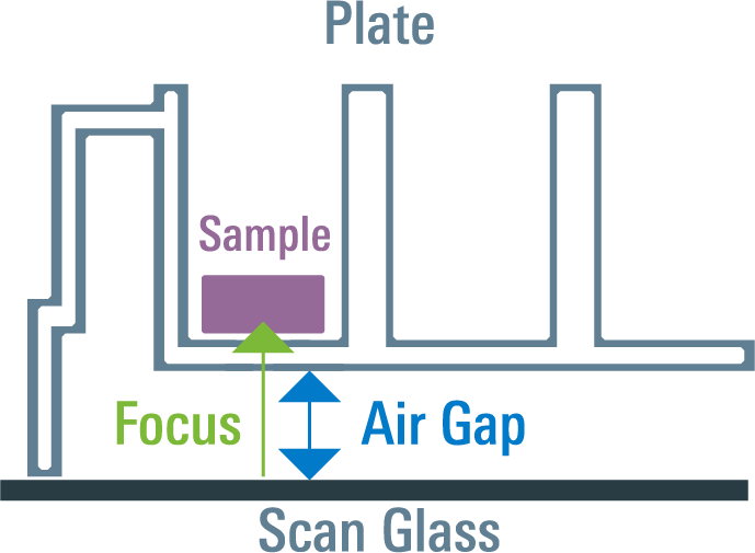
Figure 44. Air gap -
Use this information, together with knowledge of where the sample is located in the well, to estimate where the best focus is likely to be.
Step 2. Select an expected focus offset
Based on the plate drawing and assay design, choose an initial expected focus offset.
General guidance:
-
For surface-based assays (e.g., In‑Cell Western™ Assay), the best focus is usually slightly above the bottom of the well, where the sample remains in focus and the bottom of the plate is beginning to fall out of focus.
-
For solution-based assays (e.g., fluorescent ELISA), the best focus is usually somewhat farther up into the solution.
Step 3. Choose an appropriate resolution for focus optimization
When determining the best focus offset, use the lowest resolution setting that is appropriate for the assay.
-
Lower resolution provides a greater depth of focus, making the method more tolerant of plate flatness variation.
-
Higher resolution reduces depth of focus and can make focus selection more sensitive to plate non-uniformity.
Step 4. Define a focus stack range
Choose a range of focus offsets that extends below and above the expected optimal focus.
Use these focus stack step sizes for typical plate applications:
-
50 µm resolution: use 250 µm focus steps.
-
100 µm resolution: use 500 µm focus steps.
Smaller step sizes are not typically beneficial for this workflow.
If the best focus location is unknown, first scan a wider range with coarser spacing to locate the approximate focal region. Then repeat the scan over a narrower range using the recommended 250 µm or 500 µm step size.
Step 5. Acquire the focus stack
Run the focus stack using the selected range and step size. Use assay-representative scan settings, including the intended channels, plate type, and scan resolution.
-
In the Acquire tab, click Select Focus.
-
Choose Focus Stack.
-
Set the Air Gap to the distance between the scan surface and the bottom of the well, based on the plate manufacturer's documentation.
-
Enter the Starting focus and Ending focus values so the range spans below and above the expected optimal focus. Either the lower or higher value can be entered as the starting focus.
-
Enter the Increment for the stack. For typical plate applications, use:
- 0.25 mm increments for 50 µm resolution.
- 0.50 mm increments for 100 µm resolution.
- Click OK to apply the focus stack settings.
- Click Start to acquire the focus stack. The stack is acquired from the starting focus to the ending focus using the increment entered.
Notes:
-
When Focus Stack is selected, Focus Refinement is not used.
-
Focus Stack values can be entered in 0.01 mm increments.
-
To help identify all images in the same stack, add the Focus Stack Name column in the Images table.
Step 6. Compare the focus stack images
Open the focus stack images in Multi-Image View in Image Studio.
To compare focus positions consistently:
-
Link the lookup tables across the images.
-
Choose a color scheme that makes differences in signal and background easy to see.
Step 7. Choose the optimal focus offset
Choose the focus offset that gives the best image performance for the assay.
For quantitative applications, select the focus setting that provides the highest signal-to-background ratio.
Additional guidance:
-
Discard focus positions that are clearly out of focus.
-
If several nearby focus positions produce similar signal-to-background performance, choose a setting in the middle of that acceptable range. This helps reduce the effect of plate flatness variation across the plate.
-
For surface-based assays, the optimal image often occurs when the sample is still sharp but the well bottom is starting to blur.
-
For solution-based assays, the optimal image is often at a position higher within the liquid column.
Step 8. Save the scan settings as a preset
Once the optimal focus offset has been identified, create a scan preset that includes the selected resolution, channel settings, chosen focus offset, and any other scan settings needed for the assay.
Step 9. Reuse the focus offset for the remaining plates
For other plates in the same experiment, use the saved preset and the same focus offset.
Do not enable Focus Refinement for these subsequent plate scans. Focus Refinement uses the 488 nm laser and is not intended for this workflow. After the best focus has been established for the assay channel or channels, use the fixed focus offset for the remaining plate scans.
Focus Refinement is most useful for high-resolution applications such as tissue slides or arrays, rather than routine microwell plate imaging.