Verification Plates
Verification Plate for the Odyssey DLx, F and M Imagers and LICORbio Atlas™ Imaging System
Before You Begin
Re-certify the verification plate annually. Contact bioservice@licorbio.com to request the re-certification service.
Handle the verification plate with powder-free gloves.
Store the verification plate in the envelope it ships with.
Only touch the plate by the black outer casing.
Never touch the stainless steel part of the plate.
Never attempt to clean the plate yourself. If the stainless steel face becomes contaminated, return the plate to LICORbio for cleaning and re-certification.
Image Studio 6.1 or later and firmware 1.0.34 or later are required to follow this procedure with the Odyssey M Imager and LICORbio Atlas Imager.
Position the Plate
Ensure the instrument's scan bed is clean, dry, and free of any residue or dust.
-
For Odyssey® F Imager, and LICORbio Atlas™ Imaging System, use the Plate Alignment Guide (926-18972) to image the verification plate in the different plate positions.
-
For the Odyssey DLx, place the plate alignment guide (PN 9891-080) in the front left corner of the instrument. Place the verification plate with the stainless-steel section down, the text facing up (should be readable left to right), and the left/bottom sides of the verification plate contacting the alignment guide.
Begin Scan
-
Open Image Studio™ Softwarewith a Work Area created specifically for verification plate images.
-
Connect to the instrument.
-
On the Acquire tab, ensure the following settings are chosen.
-
Select the following parameters for each instrument:
Odyssey DLx - 926-21544 Channel 700 800 Resolution (μm) 169 169 Focus (mm) 3.0 3.0 Air Gap (mm) N/A N/A
Odyssey F - 926-21319 Channel 488 520 Resolution (μm) 169 169 Focus (mm) 2.15 2.65 Air Gap (mm) 2.00 2.00
Odyssey F - 926-21544 Channel 700 800 Resolution (μm) 169 169 Focus (mm) 1.80 1.95 Air Gap (mm) 2.00 2.00
Odyssey M - 926-21319 Channel 488 520 Resolution (μm) 100 100 Focus (mm) 2.20 2.35 Air Gap (mm) 2.00 2.00
Odyssey M - 926-21544 Channel 700 800 Resolution (μm) 100 100 Focus (mm) 2.10 2.15 Air Gap (mm) 2.00 2.00
LICORbio Atlas Imager - 926-21319 Channel 375Ex-460Em 488Ex-530Em 520Ex-590Em Resolution (μm) 100 100 100 Focus (mm) 2.10 2.20 2.35 Air Gap (mm) 2.00 2.00 2.00
LICORbio Atlas Imager - 926-21544 Channel 640Ex-680Em 685Ex-720Em 785Ex-820Em Resolution (μm) 100 100 100 Focus (mm) 2.10 2.10 2.15 Air Gap (mm) 2.00 2.00 2.00 -
Click Start
 .
. -
Repeat the scan in the other three corners using the alignment guide to align the plate in each corner. Do not rotate the plate.
If the channels you need to verify have different focus settings, you will have to scan them in different acquisitions since there is no option to set a focus for each channel.
For Odyssey DLx verification, you can acquire both channels at the same time.
For Odyssey F, Odyssey M, and LICORbio Atlas, you will need to scan each channel separately, because they require different focus settings.
Data Analysis
-
On the Images table, select the first of the 4 verification plate images from the 4 positions to analyze.
-
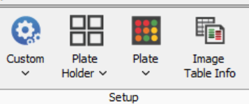
On the Analysis tab, select Plate in the Type group.
-
Ensure that in the Plate Wells table you have the columns shown in the image below. You will need at least the Image Name, Channel, Area, Plate Name, Well Name, and Trim Mean. Depending on your setup, you may need to add/remove any number of columns. To add a column, in the Plate Wells table, click Columns and select the column to add. To remove a column, unselect it.

-
To remove the background wells from the analysis, right click on the Well Name column. Select Define Filter > Does not Contain and add 06 in the box next to ‘does not contain’. Click OK. This will remove all the wells with 06 in their name from the analysis.
-
Set the plate template so that the wells circles in the image align with the plate well template. Click the up and down arrow to set the area of well template to approximately 2/3 of the diameter of the well image.
-
Repeat the process with the other 3 plate images (and with the other channels acquisitions, when needed).
-
To export the data, in the Images table in the Plate Well Tab, select all the acquisitions for the verification plate including the 4 different scan positions and the different channels acquisitions (when needed). Click on Filter > Selection.
On the Plate Wells tab, click on Filter > Display Current. (This step will unselect the Display Current). In the Plate Well table, you should see all the plate positions and channels that you acquired.
Click on Report > Save As to export the data in an Excel file.
-
Use the data from Trim Mean column to calculate the CV% for well-to-well variation. The CV% should be less than 5. If it isn't, contact LICORbio Support team at biohelp@licorbio.com.