Acquire Tab
The Acquire tab contains controls for acquiring a new image. There is an Acquire tab specific for each type of Instrument that is installed using its Instrument Key (see Application menu for information about importing Keys).
- If only one Instrument Key is installed, Image Studio™ Software will include that Acquire tab when the application is opened.
-
If more than one Instrument key is installed, choose the desired instrument type from the Instrument Model Selection dialog that appears when Image Studio™ Software starts.
To change to a different Instrument type, close Image Studio, open it again, and select a different Instrument type from the menu.
- If there is not an Instrument Key installed or if you press Cancel instead of selecting an Instrument type, the Acquire tab will not appear during that session.
Odyssey® M Imager Acquire Tab
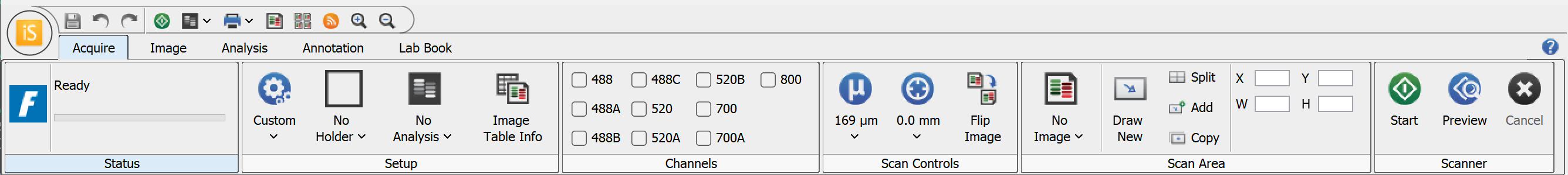
The Acquire tab shown below contains controls for acquiring an image with the Odyssey M Imager, specifically model 3350 (the model with chemiluminescence detection). The Acquire tab for the Odyssey M model 3340 will have the same functionality (except for the chemiluminescence option).

Setup
Scan Preset
Scan presets can save you time and effort. Scan presets are a saved set of scan parameters. Use the Scan Preset list
![]() in the Setup group to save the current settings as a scan preset, to select a previously saved scan preset, or to delete a selected scan preset.
in the Setup group to save the current settings as a scan preset, to select a previously saved scan preset, or to delete a selected scan preset.
Save Current Scan Preset
Once you have your scan parameters set the way you need, click Save Current Scan Preset to save the current scan settings as a scan preset. You can enter a name for the scan preset so that you can easily find this scan preset in the list and use it when needed.
The assay-specific scan presets provided with Image Studio provide scan settings that are generally a good starting point, but you can optimize settings for your assay and save your own custom scan presets as needed.
Apply Scan Preset
Choose a previously saved scan preset from the Scan Preset list by clicking its name.
Delete Scan Preset
To delete a scan preset, click Delete Scan Preset from the Scan Preset list. The Delete Scan Preset dialog will open so you can choose which scan preset(s) should be deleted.
Holder
Sample holders help ensure accurate and consistent placement of samples for consistent image acquisition. The Holder menu lets you choose which type of sample holder you are using. LICORbio recommends using the plate alignment guide (called a "plate holder" for short in the software) for imaging multiwell plates and using the slide holder for imaging slides. The same plate holder (926-18972) and slide holder (926-18971) can be used with the Odyssey F and Odyssey M.
No Holder
Choose No Holder for when you are not using a plate holder or slide holder. For example, use No Holder for gels and membranes.
There are three choices for which image to display in the scan area:
- No Image — Do not display an image in the scan grid
- Current Image — Display the current image from the image table in the scan grid
- Last Acquired — Display the last acquired image in the scan grid
Use the other controls in the (missing or bad snippet) to determine the area(s) of the scan bed to image
- Draw New — Draw the scan area by clicking the image at the upper left point and dragging the mouse to the lower right point of area to scan. Click and drag (move) the scan area rectangle for further refinement. Any previously existing scan regions are replaced by this scan area.
- Split — Split selected scan areas into multiple regions. The selected scan areas are split and evenly spaced in a row/column format. Multiple selected scan areas can optionally be merged into one area before splitting.
- Add — Add a new scan area by clicking the image at the upper left point and dragging the mouse to the lower right point of the new area to scan. Click and drag (move) the scan area rectangle for further refinement.
- Copy— Copies selected scan areas. A new scan area is created and selected that can be moved or resized.
- Scan Area Location — Displays the X, Y, Width and Height controls for the selected scan area.The Acquire Image View cursor location is also displayed.
Plate Holder
Choose Plate Holder when you are using plate holder (PN 926-18972). For example, use Plate Holder for acquiring an image of an In-Cell Western™ Assay in a 96-well microwell plate. With the Plate Holder option chosen, a 2 x 2 grid of rectangles (representing four plates) will be shown.
To choose which of these areas the imager should scan, use these options from the Scan Area group:
-
Click Add and then click the plate area(s) corresponding to the areas where your plates are on the scan surface to designate those areas to be scanned.
-
Click Draw New to select a new scan area and remove any existing selected scan areas.
-
Click Delete (or press the Delete key) to remove any selected scan areas that you no longer want to scan.
Well Formats
The following dimensions are imaged within each plate area based on the Well Format that you choose.
| Well Format | X0 (mm) | Y0 (mm) | Width (mm) | Height (mm) |
|---|---|---|---|---|
| 6 Well | 5.8 | 3.8 | 116 | 78 |
| 12 Well | 11.8 | 3.8 | 104 | 78 |
| 24 Well | 5.8 | 3.8 | 116 | 78 |
| 48 Well | 9.8 | 2.3 | 108 | 81 |
| 96 Well | 9.8 | 6.8 | 108 | 72 |
| 384 Well | 9.8 | 6.8 | 108 | 72 |
Slide Holder
Choose Slide Holder when you are using slide holder (PN 926-18971). With the Slide Holder option chosen, a 3 x 4 grid of rectangles (representing twelve slides) will be shown.
To choose where the imager should scan, use these options from the Scan Area group:
-
Click Add to draw scan areas on multiple slides (one scan area per slide).
-
Click Draw New to draw a new scan area and remove any existing scan areas.
-
Press the Delete key on your keyboard to remove any selected scan areas that you no longer want to scan.
-
Click Duplicate to duplicate the selected scan area to all slides. When a scan area is duplicated, the duplicated scan area will replace scan areas drawn on other slides.
Analysis Type
All add-on analysis types are available with Image Studio 6.0. The add-on analysis types do not need to be installed separately.
Use the Analysis Type list Select an Analysis type from the Setup group in the Acquire tab in the Setup group to specify the type of analysis to perform when an acquisition completes. You can also choose No Analysis to perform manual analysis.
If an analysis type is selected, the analysis is automatically applied when the acquisition is complete. The previous analysis will be used unless a different analysis is chosen.
No Analysis: To analyze data manually, select No Analysis from the Analysis Type list. When the acquisition completes, click the Analysis tab and choose an Analysis Type from the Analysis Type list in the Type group. Select Manual if you want to manually add shapes (the Image Studio Lane background method is unavailable when using a Manual analysis).
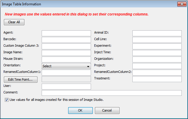
Image Table Info
To enter values for user-editable columns in the Images table:
-
Click Image Table Info Image Table Info button in the Setup group.
The Image Table Information dialog will open.
-
Image Table Information dialog In the Image Table Information dialog, enter values in any available field.
-
Click OK.
The values you entered will be saved to the Images table for the acquisition.
Channels
Options in the Channels group allow you to select the channel(s) to image. Each channel contains an image produced by a specific detection wavelength. Acquisition channels can be viewed overlaid or individually.
Scan Controls
Use options in the Scan Controls group to set the Resolution, Quality, and Focus Offset. Use Flip Image to automatically show the acquired image flipped top to bottom (useful for microplate images).
- Scan Resolution— This is the distance the scanner travels between readings. Shorter distances will give higher resolutions that provide more image details but create large image files. Longer distances will give lower resolutions that provide small image files but do not offer fine image details.
- Focus Offset — Select the Focus Offset value from the list or enter a value by choosing the Enter Value menu item.
- Flip Image — When selected the image is automatically flipped top to bottom.
Scanner
Use the controls in the Scanner group to Start the scan. Use Preview to show the image as it is being scanned.
- Start — Starts the image acquisition using the currently displayed parameter values. The status of the acquisition is displayed in the Status group. It also shows the channel being acquired, and the acquisition is listed in the Images Table.
- Preview — Creates a fast, low resolution preview image.
- Cancel — Cancels the current acquisition. All existing and pending channel images are canceled.
Odyssey® F Imager Acquire Tab
The Acquire tab shown below contains controls for acquiring an image with the Odyssey F Imager, specifically the 10-channel model (9180). Aside from different channel selection, the Acquire tab for the 3-channel Odyssey F Imager (model 9150) will have the same functionality.
Setup
Scan Preset
Scan presets can save you time and effort. Scan presets are a saved set of scan parameters. Use the Scan Preset list
![]() in the Setup group to save the current settings as a scan preset, to select a previously saved scan preset, or to delete a selected scan preset.
in the Setup group to save the current settings as a scan preset, to select a previously saved scan preset, or to delete a selected scan preset.
Save Current Scan Preset
Once you have your scan parameters set the way you need, click Save Current Scan Preset to save the current scan settings as a scan preset. You can enter a name for the scan preset so that you can easily find this scan preset in the list and use it when needed.
The assay-specific scan presets provided with Image Studio provide scan settings that are generally a good starting point, but you can optimize settings for your assay and save your own custom scan presets as needed.
Apply Scan Preset
Choose a previously saved scan preset from the Scan Preset list by clicking its name.
Delete Scan Preset
To delete a scan preset, click Delete Scan Preset from the Scan Preset list. The Delete Scan Preset dialog will open so you can choose which scan preset(s) should be deleted.
Holder
Sample holders help ensure accurate and consistent placement of samples for consistent image acquisition. The Holder menu lets you choose which type of sample holder you are using. LICORbio recommends using the plate alignment guide (called a "plate holder" for short in the software) for imaging multiwell plates and using the slide holder for imaging slides. The same plate holder (926-18972) and slide holder (926-18971) can be used with the Odyssey F and Odyssey M.
No Holder
Choose No Holder for when you are not using a plate holder or slide holder. For example, use No Holder for gels and membranes.
There are three choices for which image to display in the scan area:
- No Image — Do not display an image in the scan grid
- Current Image — Display the current image from the image table in the scan grid
- Last Acquired — Display the last acquired image in the scan grid
Use the other controls in the (missing or bad snippet) to determine the area(s) of the scan bed to image
- Draw New — Draw the scan area by clicking the image at the upper left point and dragging the mouse to the lower right point of area to scan. Click and drag (move) the scan area rectangle for further refinement. Any previously existing scan regions are replaced by this scan area.
- Split — Split selected scan areas into multiple regions. The selected scan areas are split and evenly spaced in a row/column format. Multiple selected scan areas can optionally be merged into one area before splitting.
- Add — Add a new scan area by clicking the image at the upper left point and dragging the mouse to the lower right point of the new area to scan. Click and drag (move) the scan area rectangle for further refinement.
- Copy— Copies selected scan areas. A new scan area is created and selected that can be moved or resized.
- Scan Area Location — Displays the X, Y, Width and Height controls for the selected scan area.The Acquire Image View cursor location is also displayed.
Plate Holder
Choose Plate Holder when you are using plate holder (PN 926-18972). For example, use Plate Holder for acquiring an image of an In-Cell Western™ Assay in a 96-well microwell plate. With the Plate Holder option chosen, a 2 x 2 grid of rectangles (representing four plates) will be shown.
To choose which of these areas the imager should scan, use these options from the Scan Area group:
-
Click Add and then click the plate area(s) corresponding to the areas where your plates are on the scan surface to designate those areas to be scanned.
-
Click Draw New to select a new scan area and remove any existing selected scan areas.
-
Click Delete to remove any selected scan areas that you no longer want to scan.
Well Formats
The following dimensions are imaged within each plate area based on the Well Format that you choose.
| Well Format | X0 (mm) | Y0 (mm) | Width (mm) | Height (mm) |
|---|---|---|---|---|
| 6 Well | 5.8 | 3.8 | 116 | 78 |
| 12 Well | 11.8 | 3.8 | 104 | 78 |
| 24 Well | 5.8 | 3.8 | 116 | 78 |
| 48 Well | 9.8 | 2.3 | 108 | 81 |
| 96 Well | 9.8 | 6.8 | 108 | 72 |
| 384 Well | 9.8 | 6.8 | 108 | 72 |
Slide Holder
Choose Slide Holder when you are using slide holder (PN 926-18971). With the Slide Holder option chosen, a 3 x 4 grid of rectangles (representing twelve slides) will be shown.
To choose where the imager should scan, use these options from the Scan Area group:
-
Click Add to draw scan areas on multiple slides (one scan area per slide).
-
Click Draw New to draw a new scan area and remove any existing scan areas.
-
Press the Delete key on your keyboard to remove any selected scan areas that you no longer want to scan.
-
Click Duplicate to duplicate the selected scan area to all slides. When a scan area is duplicated, the duplicated scan area will replace scan areas drawn on other slides.
Analysis Type
All add-on analysis types are available with Image Studio 6.0. The add-on analysis types do not need to be installed separately.
Use the Analysis Type list Select an Analysis type from the Setup group in the Acquire tab in the Setup group to specify the type of analysis to perform when an acquisition completes. You can also choose No Analysis to perform manual analysis.
If an analysis type is selected, the analysis is automatically applied when the acquisition is complete. The previous analysis will be used unless a different analysis is chosen.
No Analysis: To analyze data manually, select No Analysis from the Analysis Type list. When the acquisition completes, click the Analysis tab and choose an Analysis Type from the Analysis Type list in the Type group. Select Manual if you want to manually add shapes (the Image Studio Lane background method is unavailable when using a Manual analysis).
Image Table Info
To enter values for user-editable columns in the Images table:
-
Click Image Table Info Image Table Info button in the Setup group.
The Image Table Information dialog will open.
-
Image Table Information dialog In the Image Table Information dialog, enter values in any available field.
-
Click OK.
The values you entered will be saved to the Images table for the acquisition.
Channels
Options in the Channels group allow you to select the channel(s) to image. Each channel contains an image produced by a specific detection wavelength. Acquisition channels can be viewed overlaid or individually.
Scan Controls
Use options in the Scan Controls group to set the Resolution, Quality, and Focus Offset. Use Flip Image to automatically show the acquired image flipped top to bottom (useful for microplate images).
- Scan Resolution— This is the distance the scanner travels between readings. Shorter distances will give higher resolutions that provide more image details but create large image files. Longer distances will give lower resolutions that provide small image files but do not offer fine image details.
- Focus Offset — Select the Focus Offset value from the list or enter a value by choosing the Enter Value menu item.
- Flip Image — When selected the image is automatically flipped top to bottom.
Scanner
Use the controls in the Scanner group to Start the scan. Use Preview to show the image as it is being scanned.
- Start — Starts the image acquisition using the currently displayed parameter values. The status of the acquisition is displayed in the Status group. It also shows the channel being acquired, and the acquisition is listed in the Images Table.
- Preview — Creates a fast, low resolution preview image.
- Cancel — Cancels the current acquisition. All existing and pending channel images are canceled.
Acquire Tab - Odyssey CLx
The Acquire tab contains controls for acquiring a new image with the Odyssey® DLx instrument.
Setup
Scan Preset
Use the Scan Preset list ![]() in the Setup group to save the current settings as a scan preset, to select a previously saved scan preset, or to delete a selected scan preset. A scan preset determines the Analysis Type, Channels to use, Channel Intensity settings, Resolution, Quality, and Scan Area settings.
in the Setup group to save the current settings as a scan preset, to select a previously saved scan preset, or to delete a selected scan preset. A scan preset determines the Analysis Type, Channels to use, Channel Intensity settings, Resolution, Quality, and Scan Area settings.
- Click Save Current Scan Preset to save the current scan settings as a scan preset. You can enter a name for the scan preset and it will be saved in the Scan Preset list.
- Choose a previously saved scan preset from the Scan Preset list by clicking its name.
- To delete a scan preset, click Delete Scan Preset from the Scan Preset list. The Delete Scan Presets dialog will open so you can choose which scan preset(s) should be deleted.
Analysis Type
Use the Analysis Type list ![]() in the Setup group to specify the type of analysis to perform when an acquisition completes. You can also choose No Analysis.
in the Setup group to specify the type of analysis to perform when an acquisition completes. You can also choose No Analysis.
If an analysis type is selected, the analysis automatically starts when the acquisition is complete. The previous analysis will be used unless a different analysis is chosen.
Possible analysis types are listed below. Click a link to open the help topic for that Analysis Type.
- Western Analysis
- MPX™ Western Analysis
- DNA Gel Analysis
- Plate Analysis
- Plate Array Analysis
- Grid Analysis
- Grid Array Analysis
- In-Cell Western™ Analysis
- Small Animal Image Analysis
No Analysis: To analyze data manually, select No Analysis from the Analysis Type list. When the acquisition completes, click the Analysis tab and choose an Analysis Type from the Analysis Type list in the Type group. Select Manual if you want to manually add shapes (the Image Studio Lane background method is unavailable when using a Manual analysis).
The Analysis Type choices may require the installation of separate Keys (see Application menu for information about Importing Keys).
Image Table Info
To enter values for user-editable columns in the Images table:
-
Click Image Table Info
 in the Setup group.
The Image Table Information dialog will open.
- In the Image Table Information dialog, enter values in any available field.
- Click OK. The values you entered will be saved to the Images table for the acquisition.
Channels
Options in the Channels group allow you to select the channel(s) to image and control the scan intensity. Each channel contains an image produced by a specific detection wavelength. Acquisition channels can be viewed overlaid or individually.
The Intensity fields control the detector sensitivity and affect the band intensity on the image.
- If the intensity is set too high, the detector may saturate and produce white areas in the middle of intense bands/dots. Saturated pixels are colored blue when the image is displayed in grayscale (see the Display topic for how to display images in grayscale).
- If the intensity is set too low, the image may not show any fluorescence even though there is adequate signal from the samples.
To set intensities:
-
When Auto
 is selected (the Auto button will have a blue background, see below), the channel intensities are set to Auto and a wide dynamic range image is captured.
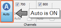
-
When Auto
is unselected, set the channel intensities manually for each channel. A lower dynamic range image will be captured.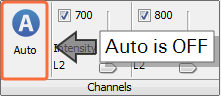
Do not use Auto mode when imaging small animals with the MousePOD® Imaging Accessory® Accessory.
Scan Controls
Use options in the Scan Controls group to set the Resolution, Quality, and Focus Offset. Use Flip Image to automatically show the acquired image flipped top to bottom (useful for microplate images).
- Scan Resolution— Select 169 µm for most scans. This is the distance the scanner travels between readings. Shorter distances (21 µm) will give higher resolutions that provide more image details but create large image files. Longer distances (337 µm) will give lower resolutions that provide small image files but do not offer fine image details.
- Scan Quality — Select the scan quality that affects the time and quality aspects of the scan. The lowest quality setting sets the fastest scan speed. Increasing the quality results in slower scan speeds, as more detector readings are processed for a given area. The Lowest scan setting gives the fastest scan time and is appropriate for most scans.
- Focus Offset — Select the Focus Offset value from the list or enter a value by choosing the Enter Value menu item.
- Flip Image — When selected the image is automatically flipped top to bottom.
Scan Area
The Display Image in Scan Area list contains options for which image to display in the scan grid.

There are three choices in the list:
- No Image — Do not display an image in the scan grid
- Current Image — Display the current image from the image table in the scan grid
- Last Acquired — Display the last acquired image in the scan grid
Use the other controls in the Scan Area group to determine the area(s) of the scan bed to image
- Draw New — Draw the scan area by clicking the image at the upper left point and dragging the mouse to the lower right point of area to scan. Click and drag (move) the scan area rectangle for further refinement. Any previously existing scan regions are replaced by this scan area.
- Split — Split selected scan areas into multiple regions. The selected scan areas are split and evenly spaced in a row/column format. Multiple selected scan areas can optionally be merged into one area before splitting.
- Add — Add a new scan area by clicking the image at the upper left point and dragging the mouse to the lower right point of the new area to scan. Click and drag (move) the scan area rectangle for further refinement.
- Copy— Copies selected scan areas. A new scan area is created and selected that can be moved or resized.
- Scan Area Location — Displays the X, Y, Width and Height controls for the selected scan area.The Acquire Image View cursor location is also displayed.
Scanner
Use the controls in the Scanner group to Start the scan. Use Preview to show the image as it is being scanned.
- Start — Starts the image acquisition using the currently displayed parameter values. The status of the acquisition is displayed in the Status group. It also shows the channel being acquired, and the acquisition is listed in the Images Table.
- Preview — Creates a fast, low resolution preview image.
- Stop — Stops the current acquisition at the current point of collection.
- Cancel — Cancels the current acquisition. All existing and pending channel images are discarded.
Acquire Tab - Odyssey® Fc Imaging System
The Acquire tab contains controls for acquiring a new image with the Odyssey Fc instrument.
Setup
Select the type of analysis to perform when the acquisition completes. If an analysis type is selected, the analysis is automatically started when the acquisition is completed. You can select:
No Analysis: To analyze data manually, select No Analysis from the Analysis Type list. When the acquisition completes, click the Analysis tab and choose an Analysis Type from the Analysis Type list in the Type group. Select Manual if you want to manually add shapes (the Image Studio Lane background method is unavailable when using a Manual analysis).
The Analysis Type choices may require the installation of separate Keys (see Application menu for information about Importing Keys).
Image Table Info
To enter values for user-editable columns in the Images table:
-
Click Image Table Info
in the Setup group.The Image Table Information dialog will open.
- In the Image Table Information dialog, enter values in any available field.
- Click OK. The values you entered will be saved to the Images table for the acquisition.
Channels
Use the controls in the Channels group to select the channels to include and position the slider to set the integration time for each selected channel.
The acquisition times range from 30 seconds to 10 minutes, except for Chemi which ranges from 30 seconds to 60 minutes. Click on the arrow on the right side of the Channels bar to open a window and change the sliders from standard to extended mode.
- In standard mode, only the 0.5, 2, and 10 minutes (and 60 minutes in Chemi) can be selected.
- In extended mode, the sliders can be adjusted to accommodate times in between. Use the arrow keys for fine adjustment.
Camera
Click Acquire Image in the Camera group to start the acquisition.
The image is acquired using the currently displayed parameters. The status of the acquisition is displayed in the Status group. It also shows the channel being acquired, and the acquisition is listed in the Images table.
While the acquisition is collected, the images are displayed in the View area.
To stop the acquisition before it has completed, click Cancel in the Camera group. All existing and pending channel images are discarded.
LICORbio Atlas™ Imager Acquire Tab
The Acquire tab (shown below) contains controls for acquiring an image with the LICORbio Atlas™ Imager (model 3360).

Setup
Scan Preset
Scan presets can save you time and effort. Scan presets are a saved set of scan parameters. Use the Scan Preset list in the Setup group to save the current settings as a scan preset, to select a previously saved scan preset, or to delete a selected scan preset.
Save Current Scan Preset
Once you have your scan parameters set the way you need, click Save Current Scan Preset to save the current scan settings as a scan preset. You can enter a name for the scan preset so that you can easily find this scan preset in the list and use it when needed.
The assay-specific scan presets provided with Image Studio provide scan settings that are generally a good starting point, but you can optimize settings for your assay and save your own custom scan presets as needed.
Apply Scan Preset
Choose a previously saved scan preset from the Scan Preset list by clicking its name.
Delete Scan Preset
To delete a scan preset, click Delete Scan Preset from the Scan Preset list.
Holder
Sample holders help ensure accurate and consistent placement of samples for consistent image acquisition. The Holder menu lets you choose which type of sample holder you are using. LICORbio recommends using the plate alignment guide (called a "plate holder" for short in the software) for imaging multiwell plates and using the slide holder for imaging slides. The same plate holder (926-18972) and slide holder (926-18971) can be used with the Odyssey F, Odyssey M, and LICORbio Atlas™ Imager.
Manual Scan Areas
Choose Manual Scan Areas for when you are not using a plate holder or slide holder.
Plate Holder
Choose Plate Holder when you are using plate holder (PN 926-18972). With the Plate Holder option chosen, a 2 x 2 grid of rectangles (representing four plates) will be shown.
To choose which of these areas the imager should scan, use these options from the Scan Area group:
-
Click Add and then click the plate area(s) corresponding to the areas where your plates are on the scan surface to designate those areas to be scanned. To exit Add mode, click Add again on the Acquire ribbon or press ESC.
-
Click Draw New to select a new scan area and remove any existing selected scan areas.
-
Click Delete (or press the Delete key) to remove any selected scan areas that you no longer want to scan.
Well Formats
The following dimensions are imaged within each plate area based on the Well Format that you choose.
| Well Format | X0 (mm) | Y0 (mm) | Width (mm) | Height (mm) |
|---|---|---|---|---|
| 6 Well | 5.8 | 3.8 | 116 | 78 |
| 12 Well | 11.8 | 3.8 | 104 | 78 |
| 24 Well | 5.8 | 3.8 | 116 | 78 |
| 48 Well | 9.8 | 2.3 | 108 | 81 |
| 96 Well | 9.8 | 6.8 | 108 | 72 |
| 384 Well | 9.8 | 6.8 | 108 | 72 |
Slide Holder
Choose Slide Holder when you are using slide holder (PN 926-18971). With the Slide Holder option chosen, a 3 x 4 grid of rectangles (representing twelve slides) will be shown.
To choose where the imager should scan, use these options from the Scan Area group:
-
Click Add to draw scan areas on multiple slides (one scan area per slide). To exit Add mode, click Add again on the Acquire ribbon or press ESC.
-
Click Draw New to draw a new scan area and remove any existing scan areas.
-
Press the Delete key on your keyboard to remove any selected scan areas that you no longer want to scan.
-
Click Duplicate to duplicate the selected scan area to all slides. When a scan area is duplicated, the duplicated scan area will replace scan areas drawn on other slides.
Analysis Type
Use the Analysis Type list in the Setup group to specify the type of analysis to perform when an acquisition completes. You can also choose No Analysis to perform manual analysis.
If an analysis type is selected, the analysis is automatically applied when the acquisition is complete. The previous analysis will be used unless a different analysis is chosen.
Possible analysis types are listed below. Click a link to open the help topic for that analysis type.
- Morphology Analysis
- Plate Analysis Overview
- Plate Array Analysis Overview
- Grid Analysis Overview
- Grid Array Analysis Overview
- In-Cell™ Western Analysis Overview
- Small Animal Image Analysis
Image Table Info
To enter values for user-editable columns in the Images table:
-
Click Image Table Info in the Setup group.
The Image Table Information dialog will open.
-
In the Image Table Information dialog, enter values in any available field.
-
Click OK. The values you entered will be saved to the Images table for the acquisition.
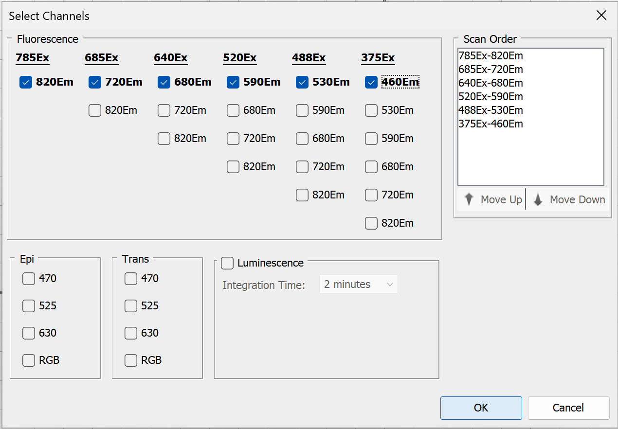
Select Channels
In the Channels group, click Select Channels to choose which channels to scan and related options.
-
Up to six channels can be imaged in a single acquisition.
-
Adjust the order in which channels are scanned using the Scan Order list. You can click and drag channels in the list, or select the channel you want to move and click Move Up or Move Down.
-
To set a specific integration time when imaging luminescence, select the Luminescence checkbox, then choose Custom from the Integration Time list.
-
When you have selected the channel options you want, click
OK .Your channel selections will the displayed in the Channels group.
Once an image is acquired, channels in the acquisition can be viewed individually or overlaid.
Select Focus
In the Focus group, click Select Focus to choose a single focus offset, focus stack, and set the air gap. The diagram and some controls in the dialog will vary based on the Holder Type selected.
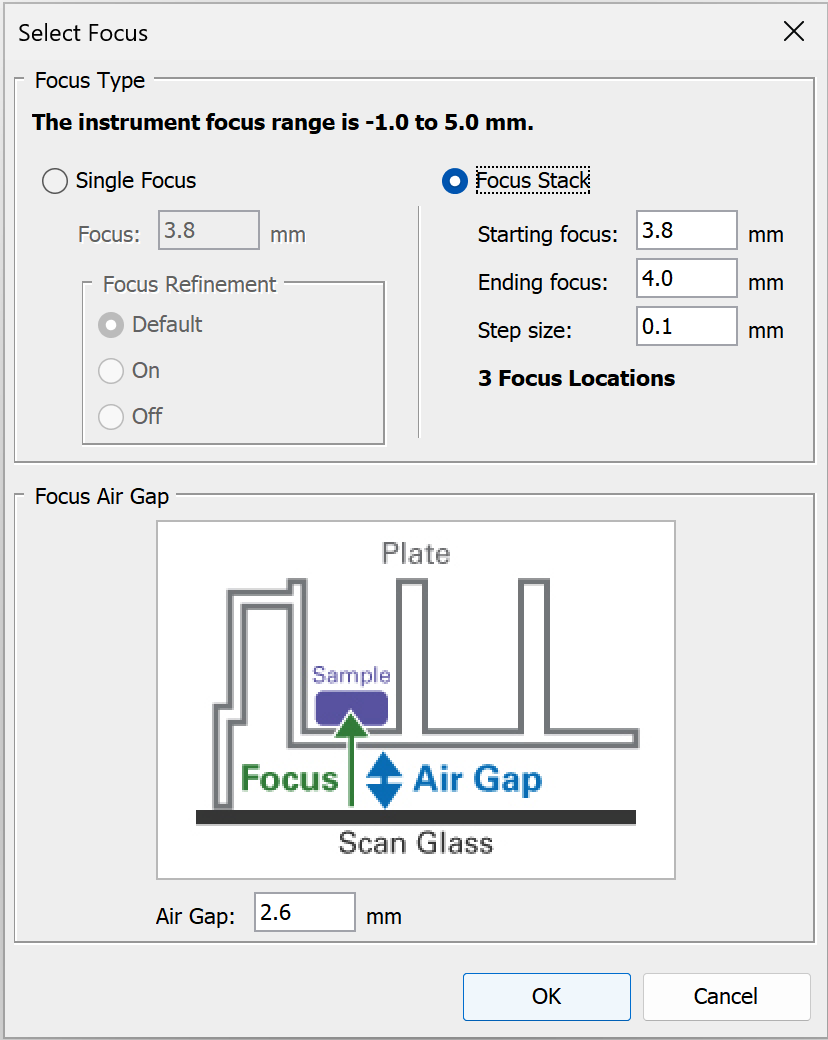
Single Focus
Choose Single Focus to acquire image(s) at just one focus position.
Focus Refinement is an option that automatically makes fine adjustments to the focus offset that is entered, if a better focus offset can be determined automatically by the imager. For some types of scans, the imager will automatically run the focus refinement routine unless you toggle it off. Focus Refinement is not available for the Odyssey F.
-
Default - Use the imager's default for when the focus refinement algorithm is used.
-
On - Run focus refinement regardless of the imager's default setting.
-
Off - Do not run focus refinement regardless of the imager's default setting.
Above the Images table, click Columns to add Focus Refined (focus offset value found when Focus Refinement is used) and Focus Refinement Setting to see which Focus Refinement setting was used to acquire an image.
Focus Stack
Choose Focus Stack when you want to automatically acquire images at a series of focus offsets. Focus Stack creates a z-stack of image acquisitions. You can use the z-stack to find the best focus offset or to create a projection image (not supported for RGB images). Available projection types include Maximum Intensity, Mean, Median, Minimum, and Standard Deviation. Standard Deviation projections can help show where intensity varies across the z-stack.
-
When Focus Stack is selected, the focus refinement algorithm is not used.
-
Focus Stack values can be entered in 0.01 mm increments.
-
The z-stack will be acquired from the Starting focus to the Ending focus in the increment you specify. You can enter the low or high focus offset as the Starting focus or Ending focus.
For example: If you enter a low focus offset as the Starting focus, then the z-stack of images will be acquired in the increment you specify until the high focus offset set as the Ending focus is reached.
-
In the Images table, click Columns and add the Focus Stack Name. The Focus Stack Name is used to group all acquisitions that are part of the same z-stack.
Air Gap
The Air Gap is the distance between the scan surface and the sample or vessel that contains the sample. For multiwell plates, set the Air Gap to the distance between the scan surface and the bottom of the well. To get this information, you may need to refer to the manufacturer's documentation or contact the manufacturer. For plates provided by LICORbio, check the pack insert.
Scan Controls
Use options in the Scan Controls group to set the Resolution, Quality, and Focus Offset. Use Flip Image to automatically show the acquired image flipped top to bottom (useful for multiwell plate images).
- Scan Resolution— This is the distance the scanner travels between readings. Shorter distances will give higher resolutions that provide more image details but create large image files. Longer distances will give lower resolutions that provide small image files but do not offer fine image details.
- Flip Image — When selected the image is automatically flipped top to bottom.
Scan Controls for Plates
The LICORbio Atlas™ Imager can acquire images of entire 6-, 12-, 24-, 48-, 96-, and 384-well standard-sized plates or individual wells from standard 6-, 12-, 24-, 48-, 96-, and 384-well plates. Only one plate format can be chosen per scan preset configuration.
To see plate imaging options, ensure the Holder Type is set to Plate Holder.
Image entire plate
When 5 µm resolution is needed, LICORbio recommends considering scanning individual wells instead of scanning the entire plate.
-
In the Scan Controls group, choose Scan Plate.
-
Click Add in the Scan Area group and then select the plate areas you want to scan. To exit Add mode, click Add again on the Acquire ribbon or press ESC.
Image individual well(s)
-
In the Scan Controls group, choose Scan Wells.
-
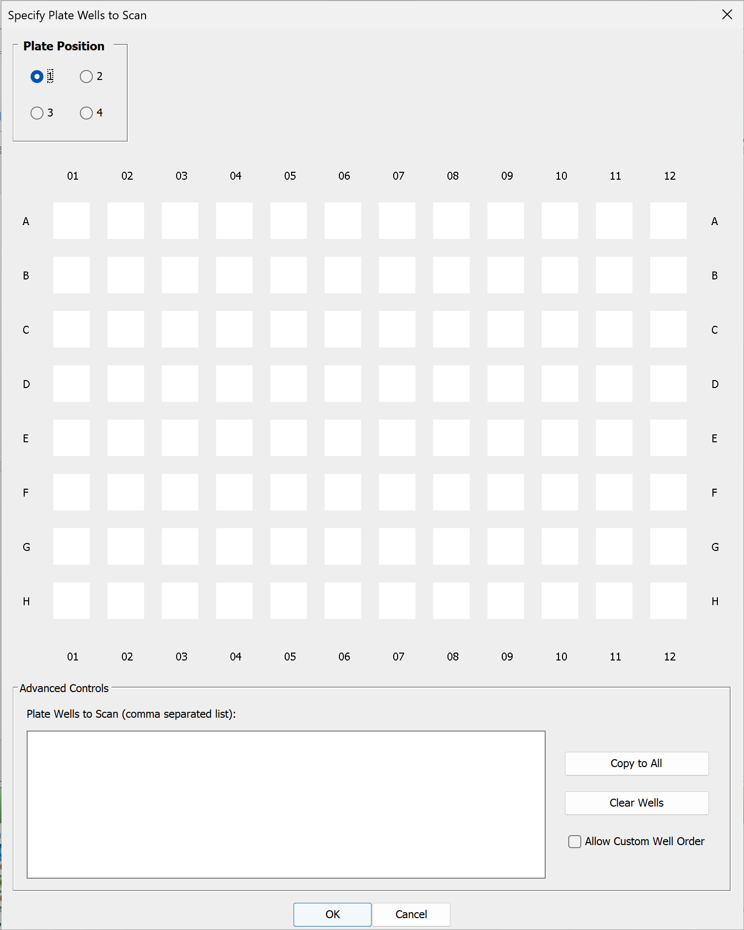
In the Scan Controls group, click Specify Wells to choose which wells to scan. The Specify Plate Wells to Scan dialog will open and provide options for choosing the wells you want to scan.
-
Check the Plate Position at the top left of the dialog to ensure that you are adding wells to the correct plate position.
You do not need to add a plate area before choosing wells. Selecting a Plate Position and choosing wells for that Plate Position will cause the correct plate area to be added after you click OK in the Specify Plate Wells to Scan dialog.
-
In the plate schematic shown in the dialog, click to choose wells to scan. Click and drag to select many wells. Click again to remove a selected well to not scan that well.
-
Click Copy to All to copy selected wells to all plate positions.
-
Click Clear Wells to remove all selected wells.
-
You can select Allow Custom Well Order and enter well names in the Plate Wells to Scan text area to scan wells in a particular order, but this is unnecessary in most cases.
-
When you have made your well selections, click OK.
-
Scan Area
There are three choices for which image to display in the scan area:
- No Image — Do not display an image in the scan grid.
- Current Image — Display the current image from the image table in the scan grid.
- Last Acquired — Display the last acquired image in the scan grid.
Use the other controls in the Scan Area group to determine the area(s) of the scan bed to image.
- Draw New — Draw the scan area by clicking the image at the upper left point and dragging the mouse to the lower right point of area to scan. Click and drag (move) the scan area rectangle for further refinement. Any previously existing scan regions are replaced by this scan area.
- Split — Split selected scan areas into multiple regions. The selected scan areas are split and evenly spaced in a row/column format. Multiple selected scan areas can optionally be merged into one area before splitting.
- Add — Add a new scan area by clicking the image at the upper left point and dragging the mouse to the lower right point of the new area to scan. Click and drag (move) the scan area rectangle for further refinement. To exit Add mode, click Add again on the Acquire ribbon or press ESC.
- Copy — Copies selected scan areas. A new scan area is created and selected that can be moved or resized.
- Scan Area Location — Displays the X, Y, Width and Height controls for the selected scan area. The Acquire Image View cursor location is also displayed.
Scanner
Use the controls in the Scanner group to Start the scan. Use Preview to show the image as it is being scanned. When enough scan settings are selected, the Status group shows an estimated scan time before you start the scan. The estimate updates as scan settings change.
- Start — Starts the image acquisition using the currently displayed parameter values. The status of the acquisition is displayed in the Status group. It also shows the channel being acquired, and the acquisition is listed in the Images Table.
- Preview — Creates a fast, low resolution preview image.
- Cancel — Cancels the current acquisition. All existing and pending channel images are canceled.
Acquire Tab - Pearl® Imaging System
The Acquire tab contains controls for acquiring a new image on the Pearl Imaging System.
Setup
Image Table Info
To enter values for user-editable columns in the Images table:
-
Click Image Table Info
in the Setup group.The Image Table Information dialog will open.
- In the Image Table Information dialog, enter values in any available field.
- Click OK. The values you entered will be saved to the Images table for the acquisition.
Heater Plate
Use the first button to turn the heater plate in the instrument on or off. The heater plate is on when the On/Off button is highlighted.
Click Set and select the desired temperature from the drop down menu. The Actual button shows the current temperature of the heater plate. The icon is red when the set temperature is more than one degree different than the current temperature. The icon changes to blue when the current temperature is within one degree of the set temperature.
Channels
Use the controls in the Channels group to select the channel(s) to acquire.
The Intensity fields control the detector sensitivity and affect the band intensity on the image.If the intensity is set too high, the detector may saturate and produce white areas in the middle of intense bands/dots. Saturated pixels are colored blue when the image is displayed in grayscale (see the Display topic for how to display images in grayscale).If the intensity is set too low, the image may not show any fluorescence even though there is adequate signal from the samples.
Camera Controls
Use the controls in the Camera Controls group to set the Resolution, Focus Position, and acquisition method.
- Resolution — Select 170 µm for most scans.
-
Focus Position — Choose the appropriate focus position from the list.
Use the focus position option if the appropriate focus position is unknown...-
Click Focus Position at the bottom of the list.
The Focus Position dialog will open and test images will be acquired at each position.
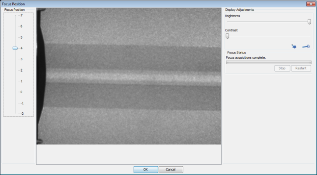
- Once all test images have been acquired, click a position on the Focus Position slider to view the image for that position. Compare the images and determine the best position.
-
With the best position selected on the slider, click OK.
The Focus Position will be set to the chosen value.
-
- Time Series — Select the time series option to use. Select Single Image to acquire one image, or Standard Time Series to acquire a series of images. The Pearl Imaging System acquires a series of images with minimal time between each image using the Fast Time Series.
Camera
Use the controls in the Camera group to start the scan.
-
Acquire Image — Starts the image acquisition using the currently displayed parameter values. The status of the acquisition is displayed in the Status group. It also shows the channel being acquired, and the acquisition is listed in the Images table.
-
Pause — Stops the current acquisition. The button changes to Resume. Click Resume to restart the current acquisition. The button changes again to Pause.
-
Stop — Stops the current acquisition.
-
Cancel — Cancels the current acquisition. All existing and pending channel images are discarded.
Camera Options
Click the Camera Options dialog launcher at the lower right corner of the Camera group to open the Camera Options dialog.
Two options are available. Enable the box to select the option. Click OK.
- Set the instrument to acquire an image automatically after the drawer is closed.
- Set the drawer to open automatically after the instrument acquires an image.
Acquire Tab - C-DiGit® Blot Scanner
The Acquire tab contains
controls for acquiring a new image with the
C-DiGit instrument.
Setup
Use the Analysis Type list![]() in the Setup group to specify the type of analysis to perform when an acquisition completes. You can also choose No Analysis.
in the Setup group to specify the type of analysis to perform when an acquisition completes. You can also choose No Analysis.
If an analysis type is selected, the analysis automatically starts when the acquisition is complete. The previous analysis will be used unless a different analysis is chosen.
No Analysis: To analyze data manually, select No Analysis from the Analysis Type list. When the acquisition completes, click the Analysis tab and choose an Analysis Type from the Analysis Type list in the Type group. Select Manual if you want to manually add shapes (the Image Studio Lane background method is unavailable when using a Manual analysis).
The Analysis Type choices may require the installation of separate Keys (see Application menu for information about Importing Keys).
Image Table Info
To enter values for user-editable columns in the Images table:
-
Click Image Table Info
in the Setup group.The Image Table Information dialog will open.
- In the Image Table Information dialog, enter values in any available field.
- Click OK. The values you entered will be saved to the Images table for the acquisition.
Sensitivity
Click Sensitivity and select Standard or High from the list.

Scanner
Click Start in the Scanner group to start the acquisition.
The scanner acquires an image using the currently displayed parameter values. The status of the acquisition is displayed in the Status group. The acquisition is listed in the Images Table. While the acquisition is collected, the image is displayed in the View area.
To stop the acquisition before it has completed, press Cancel in the Scanner group. The acquisition is discarded.