Morphology Analysis
Morphology analysis in Image Studio refers to a collection of flexible tools for identifying shapes in an image, counting shapes, and making morphological measurements of the shapes.
Shapes analyzed in morphological assays include spheroids, organoids, bacterial colonies, and others. Morphological measurements include perimeter, area, equivalent diameter, major axis, minor axis, centroid, etc., but total and signal can also be computed.
Plate format Morphology Analysis is available for full plate images. Use Well AOIs to create one Area of Interest for each well in the selected plate format and associate morphology measurements from wells with the well position. The well position, also called the well name or well ID, is stored in the Name column of the Morphology Shapes table, for example A1 through H12 for a 96-well plate.
Templates and batch analysis are available for Morphology Analysis. For more information, see Analysis Automation.
Do not combine tools from the manual Analysis ribbon and the Morphology Analysis ribbon in the same analysis, except when using the manual Analysis ribbon ruler or scale bar to measure a distance.

This page provides an overview of tools available in the Morphology Analysis ribbon.
For more information about concepts underlying morphology, see Morphology Analysis Concepts. For more information about available morphology measurements and how they are calculated, see Morphology Analysis Measurements. For some example analyses, see Morphology Analysis Workflow.
Morphology Analysis Tools
Shape Group
Drawing shapes in a Morphology Analysis has many uses.
-
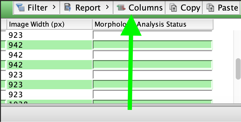
Shapes can be used to measure pixel intensities within the region bounded by the shape. These measurements include Total, Mean, Median, etc. Click Columns to add or remove measurements from the Morphology Shapes table.
-
Shapes can be assigned as Inclusion or Exclusion Areas of Interest (AOI). AOIs can be used to limit where on the image objects will be detected by Morphology Analysis shape detection (see Custom Threshold options or Auto options). AOIs can also be used to group shapes when the column "Inclusion Shapes" is enabled in the Morphology Shapes Table.
- Select
-
If you are in Draw Ellipse, Rectangle, or Freehand mode, click Select to change your cursor back to a cursor for selecting shapes instead of drawing.
You can also press ESC on your keyboard to change the cursor to Select mode.
- Draw Ellipse
-
Click Draw Ellipse to draw an ellipse on the image. To draw a circle, press and hold the SHIFT key while you click-and-drag the ellipse tool.
- Draw Rectangle
-
Click Draw Rectangle to draw a rectangle on the image. To draw a square, press and hold the SHIFT key while you click-and-drag the rectangle tool.
- Draw Freehand
-
Click Draw Freehand to draw irregularly shaped contours. Click-and-drag the cursor to draw the irregular shape.
Areas of Interest Group
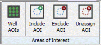
Inclusion and Exclusion AOIs determine where on the image objects will be detected by Morphology Analysis shape detection (see Custom Threshold options or Auto options).
AOIs and Morphology Templates
Image Studio 6.2 introduces analysis template capabilities for Morphology Analysis so that you can use Analysis Automation. To support Morphology templates, Image Studio stores whether AOIs were assigned before or after shape detection.
-
When an AOI is assigned before shape detection, it limits the region of the image considered when shapes are detected.
-
When an AOI is assigned after shape detection, it serves as a grouping tool but does not remove shapes that have already been detected.
- Well AOIs
-
Well AOIs are Inclusion AOIs that are sized and positioned to fit wells on standard ANSI-format plate dimensions. Instead of drawing or detecting each well manually, choose the plate format and Image Studio creates a named AOI for each well using the standard plate footprint for that format. These Well AOIs allow measurements from wells to stay associated with the well position in the plate.
-
Click Well AOIs in the Areas of Interest group.
-
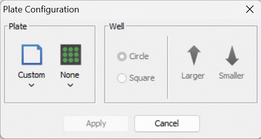
In the Plate Configuration dialog, choose the plate format, such as 6-, 12-, 24-, 48-, 96-, 384-, or 1536-well. Choose the well shape, adjust the well size if needed, and move or resize the plate overlay so the Well AOIs align with the wells in the image.
-
Click Apply.
Image Studio draws Well AOIs on all acquisition channels and assigns them as Inclusion AOIs by default. Shape detection will detect objects inside the Well AOIs.
Applying a plate configuration clears shapes that were already defined on the acquisition. If you need Well AOIs for the analysis, apply the plate configuration before detecting or drawing the other morphology shapes that you want to keep.
-
To associate detected object rows with named Well AOIs, ensure that the Inclusion Shapes column is included in the Morphology Shapes table. The Inclusion Shapes column shows which Inclusion AOI contains the detected object.
The Name column in the Morphology Shapes table stores the well position (may also be called well name or well ID) for each Well AOI, such as A1, A2, and B1.
You can save customized plate configurations and apply them to other Morphology acquisitions in the Work Area. Saved plate configurations preserve the plate format, well shape, well size, and overlay position. When a saved plate configuration is applied to an acquisition with a different resolution, Image Studio scales the configuration to the current acquisition.
If you are creating a Morphology template from an Image Studio 6.1 Work Area opened in Image Studio 6.2, see Morphology Templates from Image Studio 6.1 Work Areas.
-
- Include AOI
-
Select a shape and click Include AOI to assign the shape as an AOI. You can assign more than one shape as an AOI. With AOI(s) assigned, the Detect Shapes tool (in Custom Threshold and Auto) will only detect objects inside the AOI(s).
- Exclude AOI
-
Select a shape and click Exclude AOI to assign the shape as an Exclusion AOI. You can assign more than one shape as an Exclusion AOI. With Exclusion AOI(s) assigned, the Detect Shapes tool (in Custom Threshold and Auto) will only detect objects outside the Exclusion AOI(s).
- Unassign AOI
-
Select an AOI shape or Exclusion AOI shape and click Unassign AOI to return the shape to normal designation. Unassign AOI might be needed, for example, if the wrong shape became assigned as an AOI.
Edit Group
Tools in the Edit group allow you to modify shapes.
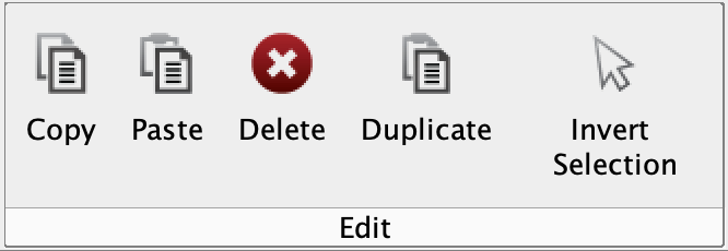
- Copy
-
Select a shape and click Copy to make a copy of the shape that you will place on the image using the Paste tool.
You can also press CTRL + C (⌘ + C) to copy a selected shape.
- Paste
-
After a shape has been copied, click Paste to place the copied shape on the image.
To paste the shape at the location of your cursor, place your cursor where you want the shape and press CTRL + V (⌘ + V) on the keyboard.
- Delete
-
Click Delete (or press Delete on the keyboard) to remove selected shape(s) from the image.
- Duplicate
-
Select a shape and click Duplicate to place a copy of the shape at the same location on every channel of the acquisition.
- Invert Selection
-
Click Invert Selection to change which shapes are selected.
Background Group
Tools in the Background group are used to designate background shape(s) used to calculate a background value that will be used to calculate Signal for the other shapes on the image.
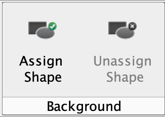
- Assign Shape
-
If you want to calculate Signal (background-adjusted pixel intensity value) for shapes in a Morphology Analysis, you will need to assign a shape or shapes to use as the background. Select the shape to use for background and click Assign Shape.
See Calculation Descriptions for more information about the Signal calculation.

Tip
If the Signal column has
NaNinstead of a number, the most likely problem is that a background shape is not assigned. - Unassign Shape
-
If you have a background shape assigned and you no longer want to use that shape as background, then select the background shape and click Unassign Shape.
Custom Thresholds Group
Tools in the Custom Thresholds group are used to mask and generate shapes around objects that you want to measure.
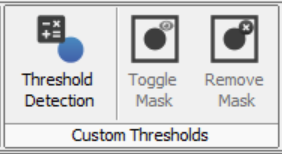
- Threshold Detection
-
Click Threshold Detection to see options for making a mask and detecting objects in the image. You can leave the Custom Threshold dialog open while adjusting parameters to find the parameters needed to detect shapes in your analysis.
If detection is taking a long time and you want to stop detection to try different parameters, click Cancel Detect. Canceled detection changes are discarded, and the image and table return to their previous state.
See Morphology Analysis Workflow for some examples.
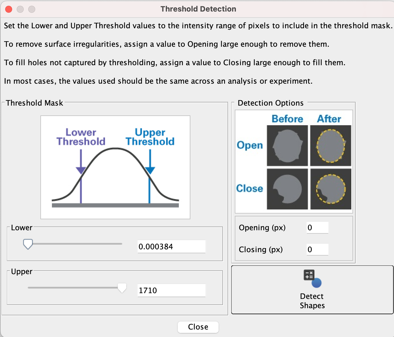
Morphology Analysis Custom Threshold Dialog -
Adjust the Upper and/or Lower thresholds as-needed to include the pixel intensities of the objects in the image that you want to measure. You can adjust the sliders, or you can enter values in the field and press Enter.
When thresholds are set well, the mask (shown as gray pixels) will overlay the objects on the image that you want to measure.
-
When the mask is shown over the objects that you want to measure, click Detect Shapes. Contours will be drawn around the objects and measurements will be available in the Morphology Shapes table at the bottom of the Image Studio window.
-
Use Include Border Shapes to choose whether detected shapes that touch the edge of the acquisition or an Inclusion AOI are included. This can help exclude partial objects from the results.
-
If contours around objects have artifacts that should not be included in your analysis (e.g., jagged edges, insubstantial tendrils coming off the shape, or small joins between shapes), then consider adjusting the Opening parameter to remove these artifacts.
Start with an Opening parameter that is roughly the length of the artifact(s) that need to be removed. You can use the Analysis ribbon > Draw Ruler tool to measure, or you can point your cursor to sides of the artifact and find the length between the coordinates shown in the lower right of the Image Studio window. Adjust as needed.
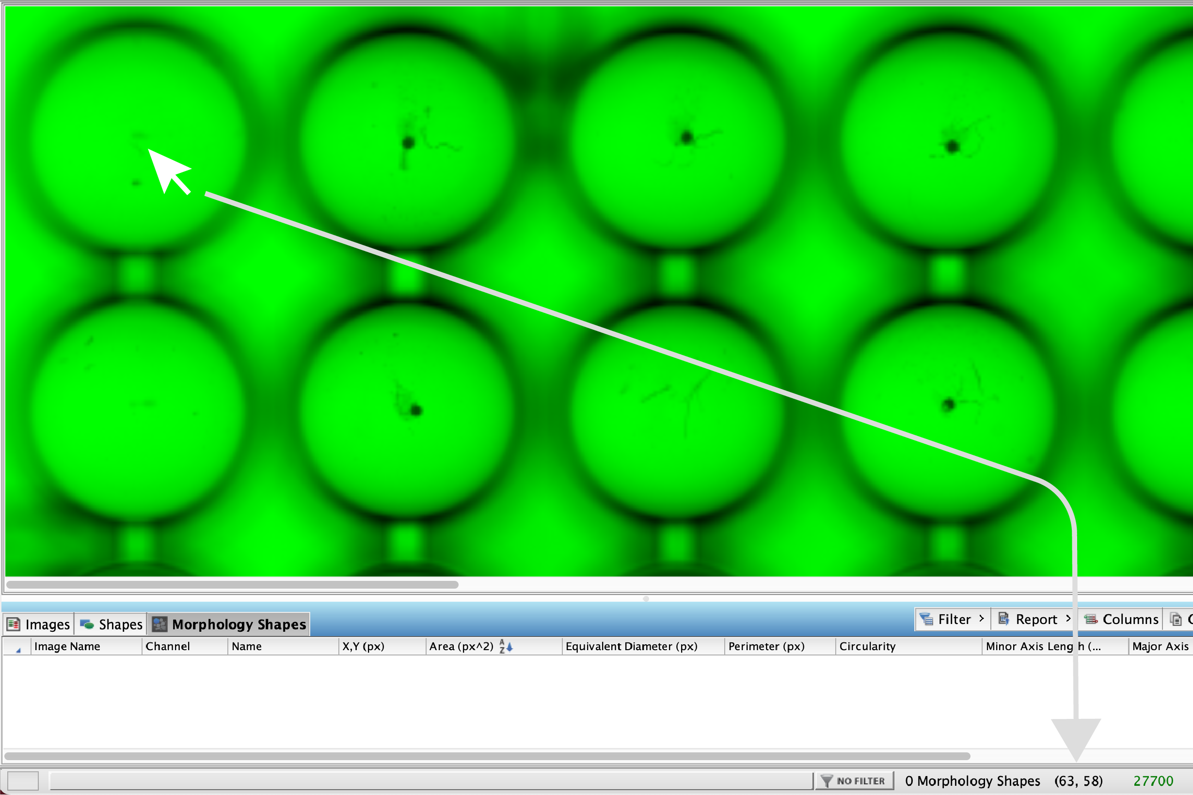
When you hover your cursor over the image, the coordinates of your cursor are shown in the lower right corner of the Image Studio window. Click Detect Shapes after you have adjusted the Opening parameter to re-generate contours around shapes.
-
If contours around objects have holes or gaps that should not be included in your analysis, then consider adjusting the Closing parameter to close these gaps.
Start with a Closing parameter that is roughly the length of the gap to fill. You can use the Analysis ribbon > Draw Ruler tool to measure, or you can point your cursor to sides of the gap and find the length between the coordinates shown in the lower right of the Image Studio window. Adjust as needed.
Click Detect Shapes after you have adjusted the Closing parameter to re-generate contours around shapes.
-
- Mask On/Off
-
Click Mask On/Off to see the image with or without the mask.
- Remove Mask
-
Click Remove Mask to remove the mask from the acquisition. Thresholds will return to their default values when the mask is removed.
Auto Group
Tools in the Auto group are used to mask and generate shapes around objects that you want to measure.
Choose the foreground option that matches how the objects look on the image. If the objects you want to detect are lighter than the background, choose Bright Foreground. If they are darker than the background, choose Dark Foreground.
- Auto Detection
-
Click Auto Detection to see options for making a mask and detecting objects in the image. You can leave the Auto Detection dialog open while adjusting parameters to find the parameters needed to detect shapes in your analysis.
Auto Detection detects shapes using an adaptive thresholding algorithm. Generally, you will choose between removing background using a single constant or a rolling ball image erosion technique.
If detection is taking a long time and you want to stop detection to try different parameters, click Cancel Detect. Canceled detection changes are discarded, and the image and table return to their previous state.
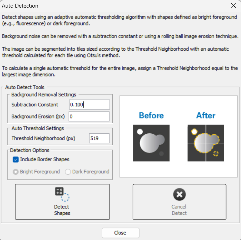
Morphology Analysis Auto Detection Dialog -
For Trans and Epi images, choose Bright Foreground or Dark Foreground.
Choose Bright Foreground when the objects you want to measure look lighter than the background. Choose Dark Foreground when they look darker than the background.
-
Use Include Border Shapes to choose whether detected shapes that touch the edge of the acquisition or an Inclusion AOI are included. This can help exclude partial objects from the results.
-
If there is a uniform and consistent background, enter that background value in the Subtraction Constant. The Subtraction Constant is subtracted from all pixels in the image before the adaptive thresholding algorithm is run. You can assess the background by pointing your cursor around the background of the image and looking at the pixel intensity displayed in the lower right corner of the Image Studio window. You could also draw a shape around the background and look at the Mean, Median, or other measurement for the shape that is appropriate for your analysis.
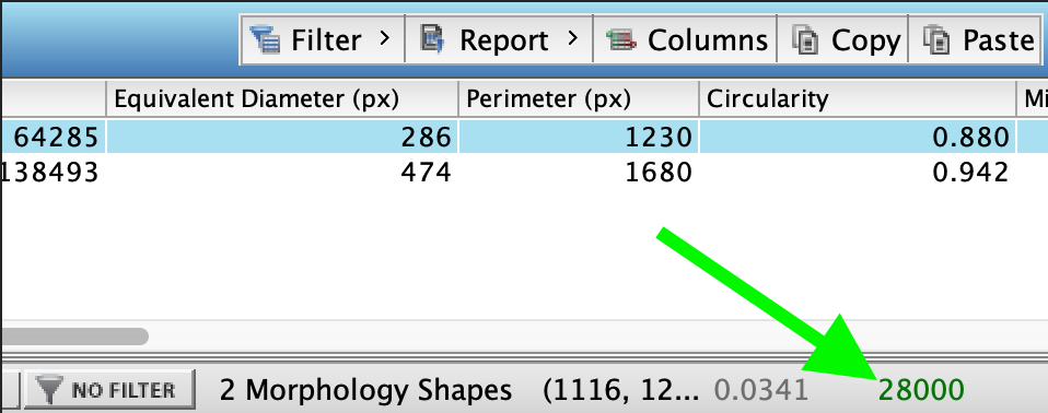
The pixel intensity is shown in the lower right corner of the Image Studio window. The pixel intensity text is shown in the same color as the display color for the image channel. -
If the background varies throughout the image and you need an adaptive method to remove background from the shape detection process, the Background Erosion can be a better option than the Subtraction Constant.
A good starting point for Background Erosion is a value slightly larger than the largest object that you want to detect. You can use Analysis ribbon > Draw Ruler to estimate the size of objects on the image.
-
For densely populated images, set the Threshold Neighborhood to the width of the largest object to identify. Increase the Threshold Neighborhood if too many objects are found.
For sparsely populated images, set the Threshold Neighborhood to half the width of the image. Decrease the Threshold Neighborhood if too many objects are found.
-
Refine Group
Further refine detected shapes using watershed segmentation.
- Refine Shapes
-
Click Refine Shapes to see options for identifying foreground and background for watershed segmentation.
If refinement is taking a long time and you want to stop refinement to try different parameters, click Cancel Refine. Canceled refinement changes are discarded, and the image and table return to their previous state.
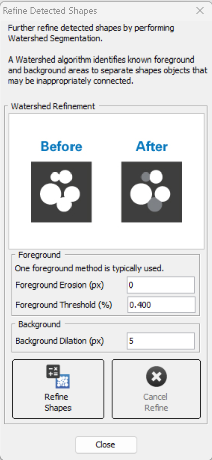
Morphology Analysis Refine Detected Shapes Dialog -
If all the objects that you want to measure are roughly the same size, then using a pixel value for Foreground Erosion may be sufficient. For Foreground Erosion, it is generally best to start with a value that is small compared to the objects you need to measure and then increase as needed.
If all the objects that you want to measure are roughly the same size, then using Foreground Threshold percentage may work better.
-
Set a Background Dilation value for identifying background. It is generally best to start with a value that is small compared to the objects you need to measure and then increase as needed.
-
Click Refine Shapes to perform the watershed segmentation. You can leave the Refine Detected Shapes dialog open while you adjust parameters and repeat watershed segmentation as-needed.
-
Export Group
Use options in the Export group to summarize and export data from the Morphology Shapes table.
- Export Summary Data
-
Click Export Summary Data to export a spreadsheet with the option of having data in length units (µm, mm, and cm) instead of pixels.
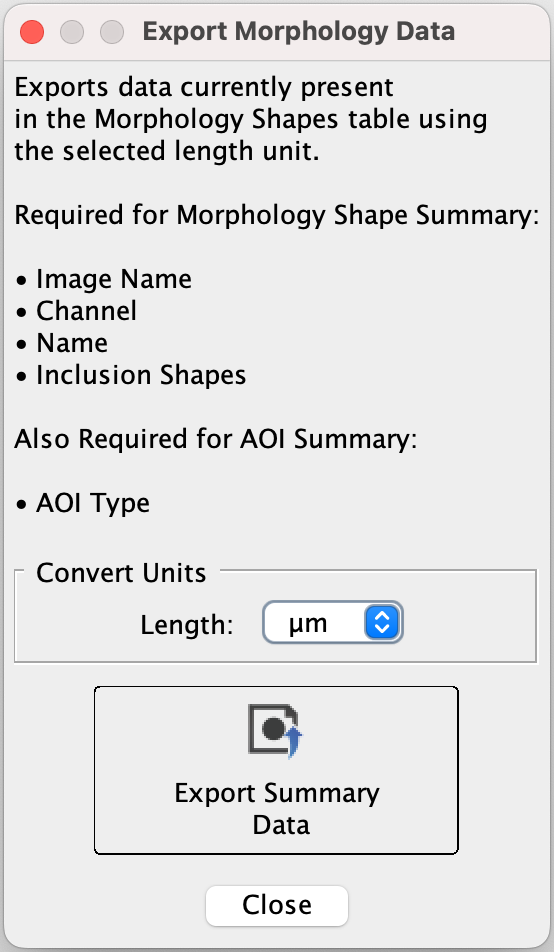
Morphology Analysis Export Morphology Data Dialog Ensure all the necessary columns (listed in the dialog) are in the Morphology Shapes table. If any are missing, click Columns (near the lower right corner of the Image Studio window) and choose the columns to add.
Both the Image Name and Resolution columns are required to uniquely identify shapes and convert Morphology values correctly. If either column is missing from the Morphology Shapes table, Image Studio displays the following warning when export is attempted:
"Ensure both the Image Name and Resolution columns are in the Morphology Shapes table. Add the missing column(s), then retry exporting.
Choose Length units and then click Export Summary Data. When you are done exporting data, click Close."